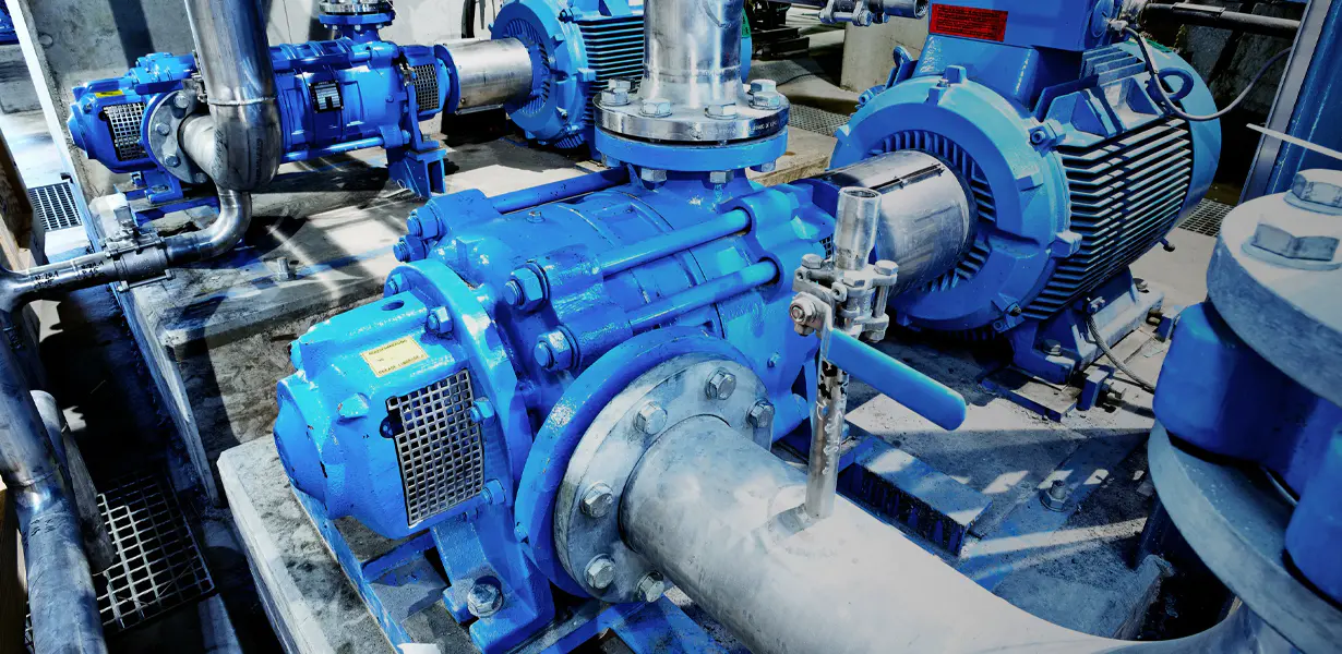
What Is a Magnetic Drive Pump and How Does It Work?
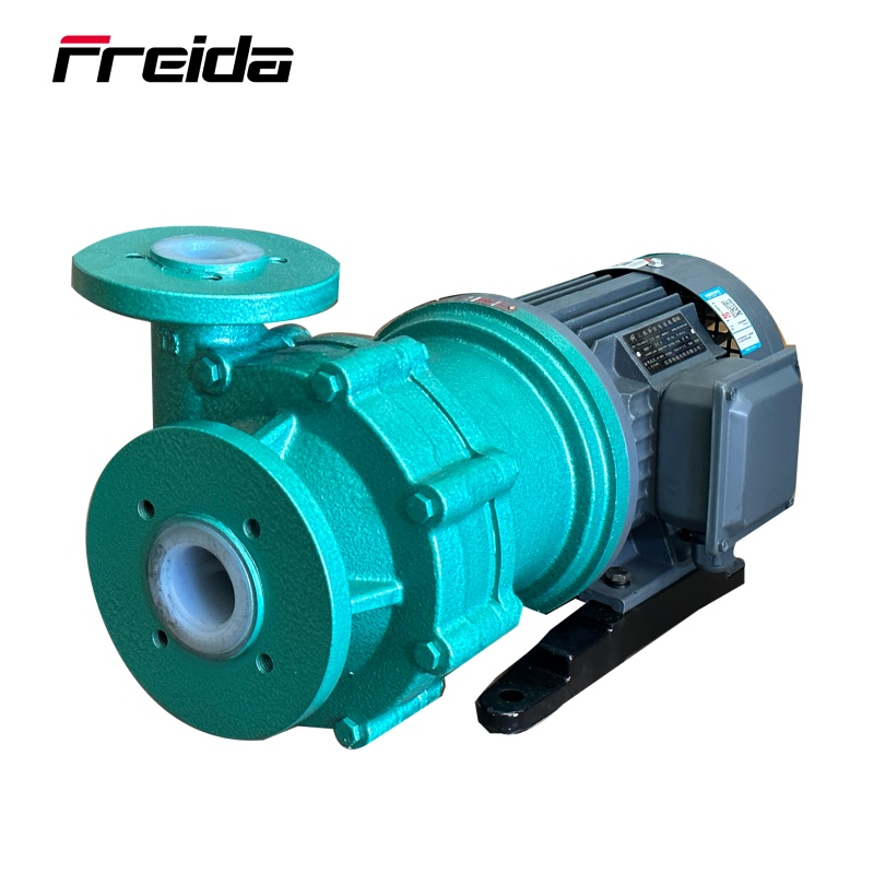
A magnetic drive pump — often called a mag drive pump or magnetically coupled pump — is a type of centrifugal pump that eliminates the traditional mechanical shaft seal by using two sets of magnets to transfer torque from the motor to the impeller. The outer magnet assembly is connected to the motor shaft, while the inner magnet assembly is coupled to the impeller inside the pump housing. When the motor rotates, the magnetic field drives the inner assembly without any direct physical connection, meaning the pumped fluid never contacts the drive mechanism.
This sealless design is the defining feature of magnetic drive pumps. In a conventional pump, a rotating shaft penetrates the pump casing and requires a mechanical seal or packing to prevent leakage — an inherent weak point. Mag drive pumps remove that penetration entirely, creating a hermetically sealed fluid path. The result is zero leakage under normal operating conditions, which makes them indispensable in industries handling hazardous, toxic, corrosive, or ultra-pure liquids.
Key Components of a Magnetically Coupled Pump
Understanding what's inside a mag drive pump helps you select the right unit and diagnose problems faster. Each component plays a precise role in achieving leak-free fluid transfer.
Outer Magnet Assembly (Driver)
Mounted directly on the motor shaft, the outer magnet assembly rotates with the motor. It houses a ring of permanent magnets — typically rare-earth neodymium-iron-boron (NdFeB) or samarium cobalt — arranged in alternating north-south poles. The strength and arrangement of these magnets determine the maximum torque the coupling can transmit.
Containment Shell (Can)
The containment shell sits between the outer and inner magnet assemblies. It is a thin-walled, non-magnetic barrier — usually made from ETFE, PTFE, Hastelloy C, or titanium — that physically separates the motor side from the wet side. Because the shell must transmit a magnetic field while withstanding process fluid, its material selection is critical to both efficiency and chemical compatibility.
Inner Magnet Assembly and Impeller
The inner magnet assembly is fixed to the impeller and rotates freely inside the containment shell on sleeve bearings or bushings lubricated by the process fluid itself. Because these bearings rely on the pumped liquid for cooling and lubrication, running a magnetic drive pump dry — even briefly — can cause catastrophic bearing failure and possible magnet decoupling.
Pump Housing and Impeller
The pump housing and impeller follow standard centrifugal pump design principles. Closed impellers are common for efficiency and handling clean liquids, while open or semi-open impellers may be used for fluids with light solids. Housing materials range from polypropylene and PVDF for chemical service to stainless steel and exotic alloys for high-temperature or high-pressure applications.
Magnetic Drive Pump vs. Mechanical Seal Pump: A Direct Comparison
Choosing between a sealless magnetic drive pump and a traditionally sealed centrifugal pump involves weighing upfront cost against long-term reliability, safety, and total cost of ownership. The table below outlines the most important practical differences.
| Factor |
Magnetic Drive Pump |
Mechanical Seal Pump |
| Leakage Risk |
Zero (hermetically sealed) |
Possible — seal wear over time |
| Maintenance Frequency |
Low — no seal replacement |
Regular seal inspection/replacement |
| Initial Cost |
Higher |
Lower |
| Total Cost of Ownership |
Often lower over 5–10 years |
Higher due to maintenance labor |
| Dry Run Tolerance |
Very low — risk of damage |
Moderate — seals can tolerate brief dry run |
| Fluid with Solids |
Limited — can damage bearings |
Better tolerance with appropriate seals |
| High-Viscosity Fluids |
Limited by magnet torque capacity |
Wider viscosity range possible |
| Safety for Hazardous Fluids |
Excellent — no emission path |
Requires double seals + monitoring |
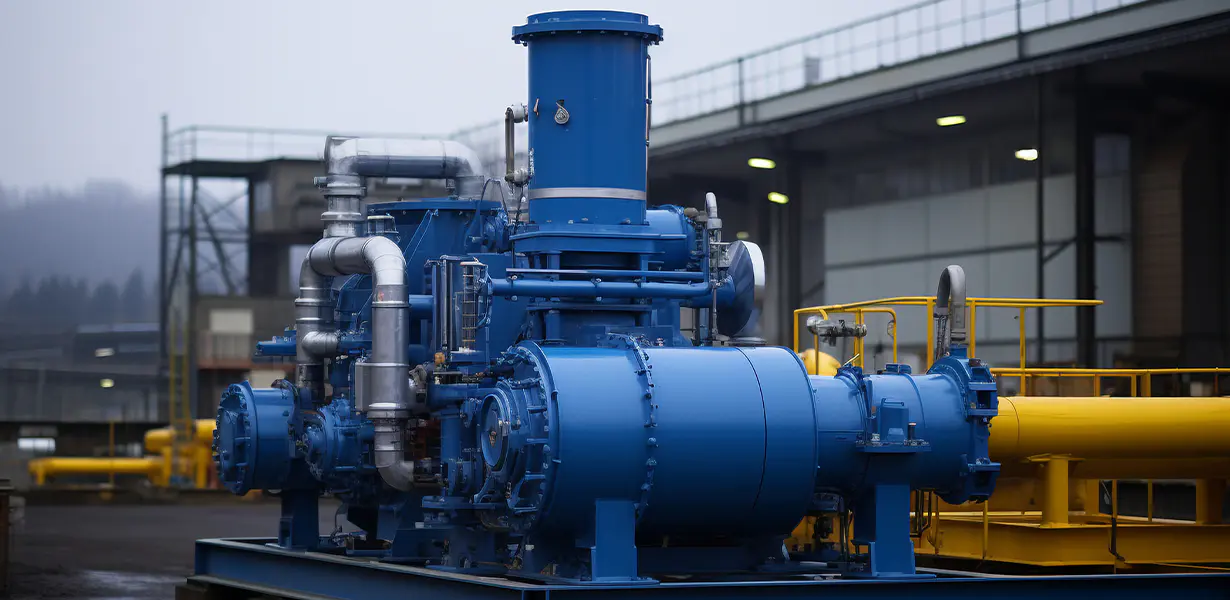
Industries and Applications That Rely on Sealless Mag Drive Pumps
The magnetic drive pump's leak-free operation makes it the preferred — and sometimes legally mandated — choice across a wide range of demanding industries. Below are the sectors where these pumps deliver the greatest operational value.
Chemical Processing
This is the largest market for magnetic drive pumps. Chemical plants transfer acids (hydrochloric, sulfuric, nitric), alkalis, solvents, and proprietary compounds that are corrosive, volatile, or toxic. A seal failure in these environments can trigger regulatory shutdowns, environmental liability, and worker safety incidents. Mag drive pumps in PVDF or Hastelloy construction handle these aggressive media without risk of fugitive emissions.
Semiconductor and Electronics Manufacturing
Ultrapure water (UPW) and high-purity process chemicals used in chip fabrication cannot tolerate any contamination from seal materials or lubricants. Fluoropolymer-lined magnetic drive pumps — where all wetted parts are PTFE or PFA — meet the stringent purity requirements of semiconductor fabs without introducing extractables or particulates into the fluid stream.
Pharmaceutical and Biotech
FDA-regulated manufacturing environments require pumps that can be cleaned in place (CIP) and sterilized in place (SIP) without disassembly. Magnetically driven pumps with electropolished stainless steel wetted parts and smooth internal geometries support hygienic design standards while eliminating the mechanical seal as a potential contamination or validation risk.
Water Treatment and Environmental Applications
Dosing sodium hypochlorite, ferric chloride, and other water treatment chemicals demands pumps that resist chemical attack and prevent leakage near public water supplies. Magnetic drive metering and centrifugal pumps are widely used in municipal water treatment plants, desalination facilities, and industrial wastewater treatment systems.
Oil, Gas, and Petrochemical
Volatile organic compounds (VOCs) and flammable hydrocarbons represent both explosion hazards and EPA emission compliance challenges. API 685 — the industry standard specifically written for sealless pumps — governs mag drive pump design in refinery and petrochemical service, where zero fugitive emissions are not just preferred but required.
How to Select the Right Magnetic Drive Pump for Your Application
Selecting the wrong mag drive pump is one of the most common causes of premature failure. A systematic evaluation across the following parameters ensures you match the pump to the actual process conditions.
- Flow Rate and Head Requirements: Establish your system curve — the relationship between required flow (GPM or m³/hr) and the total differential head (pressure) the pump must overcome — and select a pump whose performance curve intersects the system curve at the best efficiency point (BEP). Operating far from BEP increases radial loads and accelerates bearing wear in mag drive designs.
- Fluid Temperature: Temperature directly affects magnet strength. Neodymium magnets lose performance above approximately 80°C and can permanently demagnetize above 150°C. For hot fluids, specify samarium cobalt magnets or select a pump rated for elevated temperatures. Also verify that containment shell and bearing materials are rated for the operating temperature range.
- Chemical Compatibility: Every wetted component — impeller, housing, containment shell, bearings, and any O-rings — must be chemically compatible with the process fluid. Request a compatibility chart from the manufacturer and cross-reference it with your fluid's concentration and temperature. Fluoropolymer-lined pumps offer the broadest chemical resistance for aggressive media.
- Fluid Viscosity: Higher viscosity increases the torque required to drive the impeller. If the torque demand exceeds the magnetic coupling's capacity, the magnets decouple — the outer assembly spins while the inner assembly stalls, causing immediate bearing damage from dry running. Always verify the viscosity limit specified by the manufacturer for your chosen pump model.
- Solids Content: Magnetic drive pumps with fluid-lubricated sleeve bearings are sensitive to particulates. Even small amounts of abrasive solids accelerate bearing wear dramatically. If your fluid contains suspended solids, look for models with larger bearing clearances, hard ceramic or silicon carbide bearings, or consider a different pump type altogether.
- NPSH Available vs. Required: Net Positive Suction Head (NPSH) calculations are critical for any centrifugal pump. If NPSHa falls below the pump's NPSHr, cavitation occurs — forming vapor bubbles that implode violently inside the pump, damaging impeller and bearings. This is especially destructive in mag drive designs where the bearings are not externally lubricated.
Common Failure Modes and How to Prevent Them
Despite their robust design, magnetic drive pumps do fail — and when they do, the causes are almost always traceable to preventable operating conditions. Understanding the failure modes empowers maintenance teams to implement the right safeguards.
Dry Running
The most common and destructive failure mode. Because the internal bearings rely on the process fluid for lubrication and cooling, running without liquid — even for 30 seconds — can generate enough heat to melt thermoplastic components, crack ceramic bearings, or permanently demagnetize the inner magnet assembly. Prevention measures include dry-run protection sensors, flow switches on the suction line, low-level alarms on suction tanks, and proper prime procedures before startup.
Magnet Decoupling
Also called "slip" or "uncoupling," this occurs when the torque demand exceeds the magnetic coupling's rated capacity. The outer magnets continue spinning while the inner assembly stops, leading immediately to dry-run conditions. Causes include excessive fluid viscosity, system blockages, cavitation, or attempting to start against a closed discharge valve. Installing a torque-monitoring relay or current overload protection on the motor can detect decoupling events in real time.
Bearing Wear from Abrasives or Ferrous Contamination
Ferrous particles in the process fluid are attracted to the internal magnets and accumulate on bearing surfaces, dramatically accelerating wear. Even non-abrasive but ferrous-contaminated fluids are problematic. Installing inline strainers or magnetic separators upstream of the pump and specifying silicon carbide bearings (which are harder and more abrasion-resistant than carbon-graphite) can significantly extend service life.
Containment Shell Failure
The containment shell is typically the thinnest component in the pump and is subject to both chemical attack and mechanical stress from rotating imbalance. A cracked or corroded shell compromises the hermetic seal and — in metallic shells — can cause severe eddy current heating, which raises fluid temperature and can demagnetize the inner assembly. Periodic inspection during planned maintenance and selecting the correct shell material for your chemical and temperature conditions is essential.
Magnetic Drive Pump Materials: Choosing for Chemical and Thermal Resistance
Material selection is arguably the most consequential decision when specifying a magnetic pump for chemical service. Incompatible materials lead to rapid degradation, contamination of the process stream, and catastrophic failure. The following overview covers the main material families and their appropriate applications.
| Material |
Best For |
Max Temperature |
Limitations |
| Polypropylene (PP) |
Dilute acids, alkalis, water treatment |
60°C |
Poor solvent resistance |
| PVDF |
Concentrated acids, halogens, oxidizers |
100°C |
Not for strong bases |
| PTFE / PFA Lined |
Broadest chemical resistance, ultrapure |
150°C |
Higher cost, permeation risk with some solvents |
| 316 Stainless Steel |
Mild chemicals, pharma, food-grade |
200°C+ |
Not for chloride-rich or strong acid service |
| Hastelloy C-276 |
Severe corrosion, HCl, wet chlorine |
300°C+ |
High cost |
| Titanium |
Seawater, oxidizing acids, bleach |
300°C+ |
Not for fluoride service |
Installation Best Practices for Magnetically Driven Pumps
Correct installation is as important as correct specification. Many early-life failures in mag drive pumps trace back to installation errors rather than product defects. Following these guidelines during commissioning protects your investment and ensures reliable long-term operation.
- Suction Pipe Sizing and Layout: Keep suction lines as short and direct as possible with minimal bends. Size the suction pipe at least one nominal pipe size larger than the pump inlet. Avoid suction lifts where possible, and never install a valve that could restrict flow without adequate NPSH margin analysis.
- Eliminate Air Entrainment: Air or vapor in the suction line causes cavitation and dry-run conditions simultaneously. Ensure the suction pipe slopes continuously upward to the pump with no high points where air pockets can accumulate. Flood suction installations — where the fluid source is above the pump — are always preferred.
- Proper Priming Before Startup: Always verify the pump casing is completely filled with liquid before starting. Open the vent plug (if equipped) to bleed trapped air. Never rely on the pump to self-prime unless it is specifically rated for that capability.
- Pipe Stress and Alignment: Piping should be supported independently and not allowed to exert forces or moments on the pump flanges. Pipe strain misaligns the pump casing and motor, increasing vibration, bearing loads, and the risk of containment shell cracking. Use flexible connectors where vibration isolation is needed.
- Motor Alignment: Although there is no shaft coupling to align in the traditional sense, the motor and pump must be mounted on a rigid baseplate and checked for level. Misalignment between the outer and inner magnet assemblies reduces coupling efficiency and can cause vibration at elevated speeds.
- Install Protective Instrumentation: At minimum, install a flow switch or low-level switch on the suction tank wired to trip the motor if dry-run conditions develop. For critical service, consider power-monitoring relays that detect the characteristic drop in motor current when the magnets decouple.
Maintenance Schedule and Long-Term Care of Mag Drive Pumps
One of the compelling arguments for magnetic drive pumps is their low maintenance burden compared to sealed alternatives. However, "low maintenance" does not mean "no maintenance." A structured inspection routine catches developing problems before they become unplanned shutdowns.
Daily and Weekly Checks
Monitor motor current draw and compare it to the baseline recorded at commissioning. Gradual increases can indicate bearing wear or increased system resistance. Listen for changes in sound — a healthy mag drive pump runs quietly; grinding, rattling, or high-pitched noise indicates bearing distress or cavitation. Check for external leaks at pipe joints, flanges, and any drain plugs.
Annual Disassembly and Inspection
During planned shutdowns, disassemble the pump rear housing to inspect the containment shell for cracks, erosion, or chemical attack, the sleeve bearings and thrust washers for wear or scoring, the inner and outer magnet assemblies for corrosion or demagnetization, and the impeller for erosion, corrosion, or build-up. Replace wear components at manufacturer-recommended intervals rather than running to failure.
Spare Parts Strategy
Maintain a spare parts kit on site that includes at minimum: a complete set of bearings and thrust washers, one containment shell, and any elastomeric O-rings used in the pump assembly. For critical process applications, storing a complete spare pump or rotating assembly dramatically reduces mean time to repair (MTTR) following an unexpected failure.

 English
 русский
 Español
 Français

 Short Bracket Centrifugal Pump")


