How a Centrifugal Pump Works: The Basic Principle
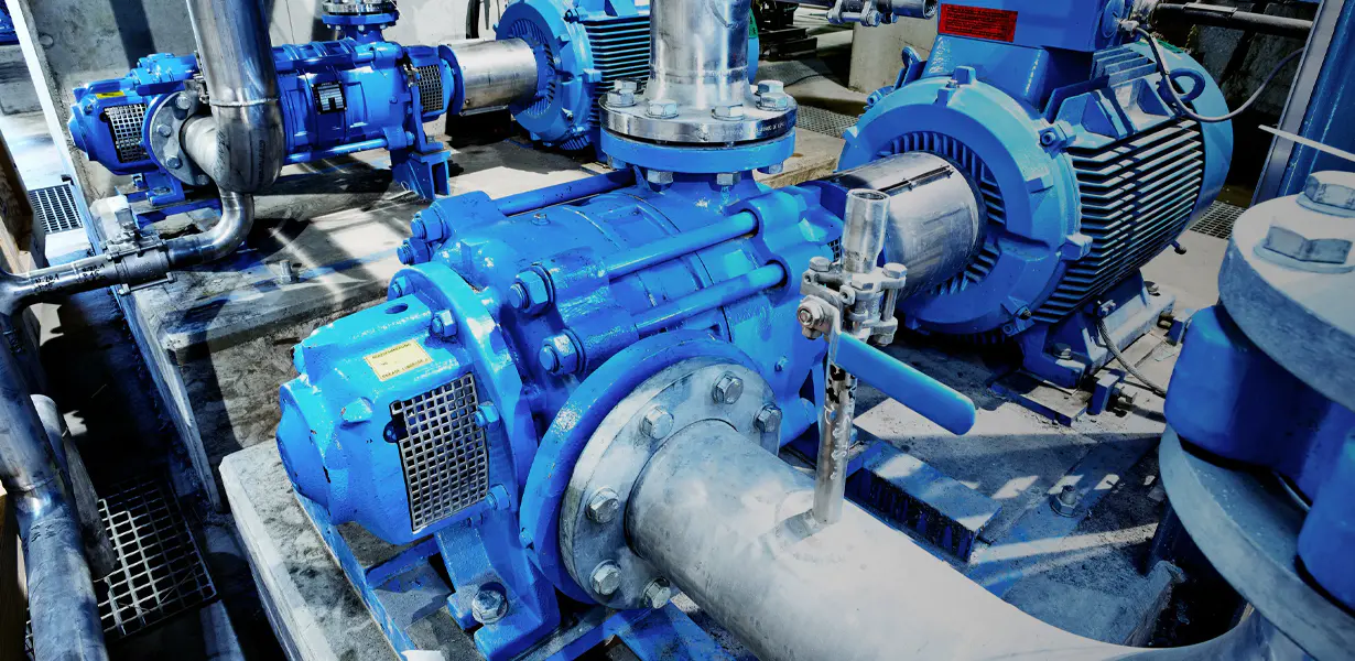
A centrifugal pump is a mechanical device that moves fluid by converting rotational kinetic energy — generated by a motor-driven impeller — into hydrodynamic energy in the form of flow and pressure. The working principle is elegantly straightforward: fluid enters the pump through the inlet (eye of the impeller) at the center, the spinning impeller imparts velocity to the fluid through centrifugal force, and that high-velocity fluid is then directed into the volute casing, where its speed is converted into pressure as it decelerates. This pressurized fluid exits through the discharge outlet and into the connected piping system.
The impeller is the heart of any centrifugal pump. It consists of a series of curved vanes mounted on a rotating disc. As the impeller spins — typically at speeds ranging from 1,450 to 3,500 RPM in standard applications — it flings fluid outward radially toward the pump casing using centrifugal force, creating a low-pressure zone at the impeller eye that continuously draws new fluid in from the suction side. This self-sustaining suction and discharge cycle is what makes centrifugal pumps so effective for high-volume, continuous-flow applications.
Unlike positive displacement pumps, which move a fixed volume of fluid per stroke or rotation regardless of system pressure, a centrifugal water pump delivers variable flow depending on the resistance (head) in the system. As system resistance increases, flow rate decreases and vice versa. This relationship is described by the pump's performance curve, also called the H-Q curve, which plots head against flow rate and is one of the most important documents for properly sizing and selecting a centrifugal pump for any application.
Main Components of a Centrifugal Pump and What Each One Does
Understanding the individual components of a centrifugal pump is essential for anyone responsible for selecting, operating, or maintaining these machines. Each part plays a specific role in the pump's overall performance, reliability, and efficiency.
Impeller
The impeller is the rotating component that directly imparts energy to the fluid. Impeller geometry — including vane curvature, number of vanes, diameter, and width — directly determines the pump's flow rate, head, and efficiency characteristics. Impellers are classified by their construction: closed impellers have shrouds on both sides of the vanes and are the most efficient design for clean fluids; open impellers lack shrouds and are easier to clean, making them suitable for slurries and fibrous fluids; semi-open impellers offer a compromise between the two. Impeller material selection is equally critical — cast iron, stainless steel, bronze, and various engineered plastics are used depending on the fluid's corrosiveness, temperature, and abrasiveness.
Volute Casing
The volute is the spiral-shaped casing that surrounds the impeller. Its cross-sectional area increases progressively from the impeller cutwater to the discharge outlet, which deliberately slows the high-velocity fluid exiting the impeller and converts its kinetic energy into pressure — a direct application of Bernoulli's principle. The volute also houses the suction inlet and discharge nozzle, and its geometry significantly influences the pump's overall hydraulic efficiency. Some centrifugal pump designs use a diffuser ring instead of or in addition to a volute, using stationary vanes to further control the energy conversion process.
Shaft and Bearings
The shaft transmits rotational torque from the motor to the impeller. It must be precisely machined to maintain tight dimensional tolerances, as any deflection or imbalance leads to vibration, accelerated seal wear, and bearing failure. Bearings support the shaft radially and axially, absorbing the hydraulic forces generated during pump operation. Most centrifugal pumps use rolling element bearings (ball or roller bearings) lubricated with grease or oil. Bearing condition is one of the most important indicators of overall pump health and is a primary focus during routine maintenance inspections.
Mechanical Seal or Packing
Where the rotating shaft passes through the stationary pump casing, a sealing arrangement prevents fluid from leaking out (or air from leaking in on the suction side). Traditional packing uses compressed fibrous or graphite rope rings around the shaft — these are inexpensive and field-serviceable but require periodic adjustment and allow a controlled leak (drip) by design. Modern mechanical seals use precision-lapped rotating and stationary seal faces pressed together by a spring, creating a near-zero leakage seal. Mechanical seals are the standard choice for most centrifugal pump applications today due to their reliability, lower maintenance requirement, and compatibility with hazardous or environmentally sensitive fluids.
Wear Rings
Wear rings (also called case rings or impeller rings) are sacrificial components fitted between the rotating impeller and the stationary casing. They maintain a tight clearance that minimizes internal recirculation of pressurized fluid back to the suction side — a leakage path that reduces volumetric efficiency. Because they experience continuous contact and wear over time, wear rings are designed to be replaceable without requiring replacement of the more expensive impeller or casing. Monitoring and replacing worn rings at appropriate intervals is a cost-effective maintenance strategy that preserves pump efficiency.
Types of Centrifugal Pumps: A Practical Overview
Centrifugal pumps are manufactured in a wide variety of configurations to suit different fluid types, pressure requirements, installation constraints, and industry standards. Selecting the correct type is as important as selecting the correct size — the wrong pump type in an application leads to premature failure, poor efficiency, and costly maintenance cycles.
Single Stage vs. Multistage Centrifugal Pumps
A single stage centrifugal pump contains one impeller and is the most common configuration. It provides moderate head (pressure) at relatively high flow rates and is the standard choice for water supply, irrigation, HVAC circulation, and general industrial transfer applications. When higher pressures are required — such as in boiler feed, high-rise building water supply, reverse osmosis systems, or pipeline boosting — a multistage centrifugal pump is used instead. Multistage designs stack two or more impellers in series within a single pump casing, with each stage adding incrementally to the total head developed. This allows very high discharge pressures to be achieved without requiring impractically large impeller diameters or shaft speeds.
End Suction Centrifugal Pumps
End suction pumps are the most widely produced centrifugal pump configuration globally. The suction inlet enters the pump axially (from the end) and the discharge exits radially (from the top or side of the casing). They are compact, straightforward to install and maintain, and available in a vast range of sizes and materials. Most ANSI and ISO standardized pump frames fall into this category. End suction centrifugal pumps are the default choice for water treatment, building services, agriculture, and light industrial fluid transfer where space is limited and standard hydraulic performance is sufficient.
Split Case Centrifugal Pumps
Split case pumps — also called double suction pumps — feature a casing that is divided horizontally along the shaft centerline, allowing the upper half to be removed for complete internal access without disturbing the piping connections. The impeller draws fluid in from both sides simultaneously (double suction), which balances axial thrust, reduces bearing loads, and allows for very high flow rates. Split case centrifugal pumps are commonly used in municipal water supply, fire protection systems, large HVAC plants, and irrigation pumping stations where reliability, ease of maintenance, and high-volume capacity are paramount.
Vertical Turbine and Submersible Centrifugal Pumps
When the fluid source is below the pump installation point — such as in a deep well, sump, wet pit, or underground reservoir — vertical or submersible centrifugal pump configurations are used. Vertical turbine pumps use a long column of stacked impeller bowls suspended below the motor, drawing fluid up from depth. Submersible centrifugal pumps are sealed units where the motor and pump are combined into a single waterproof assembly that operates fully submerged in the pumped fluid. Both designs eliminate the suction lift challenge that limits surface-mounted pumps and are widely used in groundwater extraction, sewage handling, mine dewatering, and flood control.
Self-Priming Centrifugal Pumps
Standard centrifugal pumps cannot handle air in the suction line — they must be primed (filled with liquid) before starting, or they will lose suction and fail to deliver flow. Self-priming centrifugal pumps incorporate a recirculation chamber that retains a volume of liquid after shutdown, which the pump uses to create suction and evacuate air from the inlet pipe on the next startup without manual priming intervention. This makes self-priming centrifugal water pumps particularly valuable for portable applications, dewatering, tank emptying, and any installation where the pump sits above the fluid source and maintaining a foot valve is impractical.
Centrifugal Pump Types Compared: Key Specifications
The table below provides a direct side-by-side comparison of the most common centrifugal pump configurations to help guide selection based on your specific application requirements.
| Pump Type |
Typical Flow Range |
Typical Head Range |
Key Advantage |
Common Applications |
| Single Stage End Suction |
1 – 5,000 m³/hr |
5 – 150 m |
Compact, versatile, low cost |
HVAC, irrigation, water supply |
| Multistage |
1 – 1,000 m³/hr |
50 – 1,500 m |
Very high pressure output |
Boiler feed, RO systems, high-rise |
| Split Case (Double Suction) |
100 – 50,000 m³/hr |
10 – 150 m |
Very high flow, balanced thrust |
Municipal water, fire systems |
| Vertical Turbine |
5 – 10,000 m³/hr |
10 – 300 m |
Deep well, below-grade sources |
Groundwater, irrigation, cooling |
| Submersible |
0.5 – 5,000 m³/hr |
5 – 200 m |
No priming, fully submerged |
Sewage, sump, mine dewatering |
| Self-Priming |
1 – 500 m³/hr |
5 – 80 m |
Handles air in suction line |
Dewatering, portable, tank drain |
How to Select the Right Centrifugal Pump for Your Application
Proper centrifugal pump selection is a systematic engineering process that begins with defining the system requirements and ends with confirming that a specific pump model's performance curve intersects the system curve at an operating point within the pump's preferred operating range. Skipping steps in this process leads to pumps that are oversized, undersized, or simply mismatched to the system — resulting in energy waste, vibration, cavitation, and premature failure.
Step 1 — Define Required Flow Rate and Total Head
The two most fundamental parameters in centrifugal pump selection are the required flow rate (expressed in liters per minute, gallons per minute, or cubic meters per hour) and the total head the pump must overcome (expressed in meters or feet of fluid). Total head includes static head (the vertical elevation difference between suction and discharge), friction head losses in piping, fittings, and valves, and any pressure differential between suction and discharge vessels. A complete system head calculation using the Darcy-Weisbach or Hazen-Williams friction loss methods is essential for accurate pump sizing — guessing or estimating these values is one of the most common and costly mistakes in pump selection.
Step 2 — Assess Fluid Properties
The physical and chemical properties of the fluid being pumped profoundly influence which centrifugal pump design and materials are appropriate. Key fluid properties to document before selecting a pump include: specific gravity (density relative to water), viscosity, temperature, pH, solids content and particle size, and any special characteristics such as flammability, toxicity, or tendency to crystallize. High-viscosity fluids reduce pump efficiency and may make a positive displacement pump more appropriate than a centrifugal design. Corrosive fluids require wetted parts made from compatible materials — 316 stainless steel, duplex stainless, Hastelloy C, or engineered polymer-lined casings depending on the specific chemistry involved.
Step 3 — Check Net Positive Suction Head (NPSH)
NPSH is one of the most critical and frequently misunderstood factors in centrifugal pump selection. Every centrifugal pump has a required NPSH (NPSHr) — a minimum suction pressure needed to prevent cavitation. Your installation must provide an available NPSH (NPSHa) that exceeds the NPSHr by a safe margin (typically at least 0.5–1.0 m). NPSHa is calculated from the suction source pressure, suction pipe friction losses, fluid vapor pressure, and the vertical distance between the suction source and pump centerline. Insufficient NPSH leads to cavitation — the formation and violent collapse of vapor bubbles inside the pump — which causes severe impeller erosion, noise, vibration, and rapid pump deterioration.
Step 4 — Select for Best Efficiency Point (BEP)
Every centrifugal pump operates most efficiently at its best efficiency point (BEP) — the flow rate at which the pump delivers the highest ratio of hydraulic power output to shaft power input. Operating significantly to the left or right of BEP increases vibration, radial bearing loads, internal recirculation, and heat generation. For maximum pump reliability and energy efficiency, the normal operating point should fall between 80% and 110% of the BEP flow rate. When reviewing pump performance curves during selection, confirm that your calculated duty point lands within this preferred operating range.
Centrifugal Pump Installation: Best Practices That Prevent Early Failures
Even a correctly selected centrifugal pump will underperform or fail prematurely if it is installed incorrectly. The most common installation-related pump failures involve inadequate suction piping design, misalignment between the pump and driver, and insufficient structural support — all of which are entirely preventable with proper installation practice.
- Suction piping design: Keep suction pipe runs as short and straight as possible, sized generously to keep fluid velocity below 1.5 m/s. Avoid placing elbows, reducers, or valves immediately upstream of the pump suction flange — a minimum of 5–10 pipe diameters of straight pipe before the inlet significantly reduces turbulence and improves NPSH conditions. Always use eccentric reducers (flat side up) rather than concentric reducers in horizontal suction lines to prevent air pocket formation.
- Shaft alignment: Misalignment between the pump shaft and motor shaft is the single leading cause of bearing and mechanical seal failures in centrifugal pumps. After mounting both pump and motor on a common baseplate, use a laser alignment tool or dial indicators to achieve angular and parallel alignment within the manufacturer's specified tolerance — typically within 0.05mm. Recheck alignment after connecting piping, as pipe loads frequently shift the pump position.
- Baseplate grouting: For permanently installed centrifugal pumps, grouting the baseplate to the foundation eliminates vibration transmission, prevents the base from shifting under operating loads, and maintains alignment between pump and motor over time. Use non-shrink epoxy grout poured under the fully leveled baseplate, and allow full cure time before connecting piping or starting the pump.
- Pipe support: Never use the pump casing as a structural support for the connected piping. Pipe loads applied to the pump flanges cause casing distortion, misalignment, and seal failures. Support all suction and discharge piping independently and use flexible connections where vibration isolation is needed between pump and piping system.
- Priming before startup: Unless the pump is self-priming, completely fill the pump casing and suction piping with fluid before starting. Starting a centrifugal pump dry — even briefly — causes immediate damage to mechanical seals and wear rings, as these components depend on the pumped fluid for lubrication and cooling.
Centrifugal Pump Maintenance: Keeping Performance and Reliability High
A well-maintained centrifugal pump can deliver decades of reliable service. The most effective maintenance programs combine regular condition monitoring with planned preventive maintenance tasks performed at defined intervals based on operating hours or calendar time.
Routine Monitoring During Operation
During normal operation, centrifugal pump health can be assessed through several observable parameters. Vibration monitoring using handheld analyzers or permanently installed sensors detects developing imbalance, misalignment, bearing deterioration, and cavitation before they cause catastrophic failure. Temperature monitoring of bearing housings and mechanical seal areas identifies lubrication problems and seal face overheating. Tracking discharge pressure and flow rate against the original design conditions reveals gradual efficiency losses caused by wear ring degradation, impeller erosion, or internal recirculation — a pump delivering reduced head and flow at the same speed is a pump that needs inspection.
Planned Preventive Maintenance Tasks
Preventive maintenance intervals vary by application severity, but the following schedule reflects general industry practice for industrial centrifugal pumps in continuous service. Bearing re-greasing should be performed every 2,000–4,000 operating hours using the correct grease type and quantity specified by the manufacturer — over-greasing is as damaging as under-greasing, as excess grease causes churning heat inside the bearing housing. Complete bearing replacement is typically performed every 16,000–25,000 hours or at the first sign of elevated vibration or temperature. Mechanical seal inspection should occur at every planned shutdown, with replacement at the first sign of visible leakage beyond manufacturer-specified limits. Wear ring clearances should be measured and rings replaced when clearance has doubled from the original design value.
Troubleshooting Common Centrifugal Pump Problems
When a centrifugal pump is not performing as expected, systematic troubleshooting using a structured cause-and-effect approach is far more effective than replacing components at random. The majority of centrifugal pump problems fall into recognizable symptom categories with well-understood root causes.
- No flow or insufficient flow after startup: Check first for a clogged suction strainer or partially closed suction valve. If cleared valves and strainer don't resolve the issue, check for air in the suction line (a leaking joint or gasket), insufficient suction head, or an impeller rotating in the wrong direction — a very common issue after electrical work, as a three-phase motor connected with one phase reversed spins backward and delivers virtually no flow.
- Cavitation (rattling, crackling noise during operation): Cavitation sounds like gravel being pumped and is caused by vapor bubble formation and collapse on the impeller vanes. Immediate causes include insufficient NPSHa, excessive flow rate beyond BEP, high fluid temperature, or a partially blocked suction line. Reduce flow rate, check and clear suction restrictions, lower fluid temperature if possible, or reduce suction pipe losses. Persistent cavitation causes rapid impeller pitting and must be corrected promptly.
- Excessive vibration: New or worsening vibration indicates impeller imbalance (possibly from wear, erosion, or fouling), shaft misalignment with the driver, bearing deterioration, operation far from BEP, or structural resonance in the baseplate or piping. Use vibration analysis to identify the dominant frequency before dismantling — frequency patterns clearly differentiate between imbalance, misalignment, bearing defects, and flow-induced vibration.
- Overheating motor or pump casing: A motor running hot indicates it is overloaded — which in a centrifugal pump usually means the system resistance is lower than designed, pushing the operating point far to the right of BEP and increasing flow (and therefore power demand) beyond the motor's rated capacity. Partially closing the discharge valve to increase system resistance brings the operating point back toward BEP and reduces power draw. Pump casing overheating with no flow indicates dead-heading — operating against a closed discharge valve, which rapidly heats the trapped fluid and can cause casing damage or seal failure.
- Mechanical seal leakage: A small amount of leakage from a mechanical seal face (a few drops per hour) is normal in some designs, but continuous or increasing leakage indicates seal face wear, incorrect installation, operating outside design pressure or temperature, or fluid contamination causing face corrosion. In most cases, mechanical seal replacement is more cost-effective than face lapping and reassembly unless the pump is large and the seal is an expensive custom design.
Energy Efficiency in Centrifugal Pumps: Where the Savings Are
Pumping systems account for approximately 20% of global industrial electricity consumption, and centrifugal pumps are by far the most widely used pump type in that total. Even modest improvements in centrifugal pump efficiency translate into substantial energy and cost savings over the operational life of an installation — which for an industrial centrifugal pump is typically 15–25 years.
The most impactful energy efficiency measure in centrifugal pump systems is the addition of a variable frequency drive (VFD) to control pump speed in response to actual system demand. Because pump power consumption follows the affinity laws — where power varies with the cube of shaft speed — even a modest speed reduction produces a disproportionately large reduction in energy use. Reducing pump speed from 100% to 80% of rated speed reduces power consumption to approximately 51% of full-speed power. For pumps that operate at partial load for significant portions of their duty cycle, VFD control is consistently one of the fastest-payback energy investments available in industrial facilities.
Beyond VFD control, other efficiency improvement opportunities include: replacing worn wear rings and impellers that have degraded hydraulic efficiency through erosion; right-sizing oversized pumps that have been throttled for years with partially closed discharge valves (which wastes the energy the pump puts into the fluid as valve pressure drop); trimming impeller diameters to better match reduced system requirements rather than throttling; and ensuring that pump selection targets the highest efficiency point of available models, especially for high-duty-cycle applications where even a 2–3% efficiency improvement accumulates to significant energy savings over a multi-year operating period.

 English
 русский
 Español
 Français

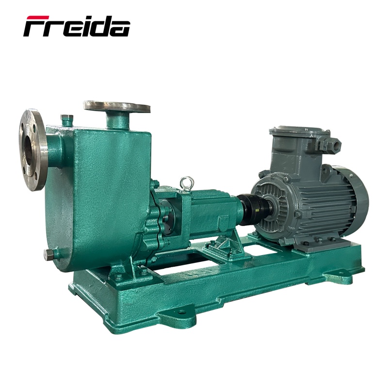
 Short Bracket Centrifugal Pump")


